Evolution of the guitar amplifier
In our previous article (see Inside a Guitar Amplifier Part 1), we learnt that guitar amplifiers, no matter how complex, consist of three parts. These are the preamp, a power amp and a speaker.
While this basic design holds true for all guitar amplifiers since their origin, a number of key design innovations have been introduced over time.
In this second article, we’ll discuss issues that rose as part of the ongoing development of the electric guitar. We’ll also look at how guitar amplifier designs evolved to solve these issues.
In the beginning – a quick recap
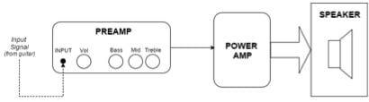
Regardless of a guitar amplifier’s additional features, the above diagram shows the architecture by which all guitar amplifiers operate.
The preamp is the part of the guitar amp responsible for creating the amplified guitar signal’s tone. It is what the control knobs link to. The preamp receives the input signal waveform from the guitar and shapes the tone. It does this via gain stages, a volume control, an equalisation (EQ) network (of Bass/Mid/Treble) and noise filtering circuitry.
Once the signal travels through the preamp’s processing, it passes on to the power amp. The power amp uses the AC voltage from the mains power to convert the tiny waveform into a larger signal, capable of driving the speaker.
This blueprint served amp manufacturers well during the early years of the electric guitar and was the structural basis for many of the first guitar amplifiers in the 1930’s. However, many early guitar amplifiers were not adept at recreating a guitar’s input signal with accuracy.
These amps produced a strong midrange-focused voicing, due to unwanted side effects occurring in the power amp section. This was somewhat at odds with the desire of the 1930’s jazz guitar players to look for the cleanest, most accurate tone possible. To combat this issue, amp engineers introduced a simple audio circuit to counteract the midrange peculiarity. This circuit is the “negative feedback” (NFB) circuit.
Negative Feedback
Negative feedback works by tapping off a small portion of the amplified input signal exiting the power amp to drive the speaker. This tapped off signal has its polarity inverted. It is then sent back to merge with the input signal that is entering the power amp.
Due to destructive wave theory, the inverted signal “cancels out” a portion of the input signal. NFB signal has a prominent midrange, so the “cancelling out” effect occurs primarily in that frequency spectrum.
The result is that the unwanted midrange generated in the power amp reduces. The circuit results in a more “true” audio signal and a wider frequency response, at the expense of some amplification gain.
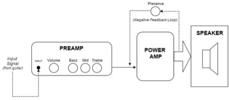
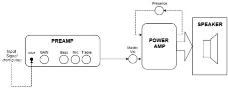
Tweed amps in the 1950s built negative feedback into their design, along with a rudimentary tone filter which altered how the NFB affected the treble frequencies. This tone filter had a control knob labelled PRESENCE. Increased settings gave the amp a livelier, more “present” sound. This PRESENCE circuit proved to be very useful and continues in many amps today.
Check out the diagram below, which shows the basic architecture of a simple guitar amp incorporating a presence control, such as a classic tweed or “Plexi” amplifier.
Master Volume designs
From the late 1950’s to the mid 1970’s, guitar amplifier design didn’t change greatly, although tone controls began to diverge between American and British guitar amps. This assisted in creating distinct tonal identities. In most cases, the basic Volume/Treble/Mid/Bass/Presence layout persisted.
One significant factor was how guitar players were using their amps. The initial goal of a guitar amp had been to provide a clean reproduction of the electric guitar’s natural tone. Guitar players of the 1960’s and 1970’s however, discovered that turning up a guitar amplifier to its operational limits would begin to “overdrive” the amplifier.
The sound of an overdriven guitar amp was uniquely pleasing and thoroughly intoxicating. Thanks to musical pioneers such as Chuck Berry, The Who and Jimi Hendrix, the sound of a distorted electric guitar became synonymous with Rock music.
However, the glorious roar of a guitar amplifier driven into overdrive came with a significant side effect – excessive volume! As such, it became necessary for guitar amplifiers to achieve overdriven sounds at manageable levels.
Amp designers achieved this by placing a second volume control between the preamp and power amp circuitry. Players used the first volume control (or GAIN) to overdrive only the preamp circuit. Using the second volume control (or MASTER VOLUME) reduced the overall level before the signal hit the power amp.
This innovation arrived to great enthusiasm and when the first guitar amplifiers featuring Master Volume controls became commercially available, they were wildly popular.
The sound of preamp distortion sounds different than overdriving the whole amp. Preamp distortion is tighter and more focussed. It can be set to near infinite levels of distortion and sustain and controlled at output to be as quiet as a whisper.
The guitar players of the late 1970’s enthusiastically exploited this new sound, with Master Volume guitar amplifiers defining the sound of 1970’s/1980’s hard rock music.
It wasn’t long before almost every guitar amplifier on the market had some sort of Master Volume design. This stratospheric level of available distortion and sustain came with its own drawbacks though.
Effects Loops (FX Loop)
A natural by-product of amplifier distortion is compression. The higher the level of preamp gain (distortion) used, the more compression appears. This alone is not a problem – in fact, it is this very compression that creates the desirable sustain that a high-gain guitar amp can achieve.
The problem is that massive compression achieved from high-gain tones negatively affects the use of some guitar effects. Delay and reverb pedals for example, essentially compress to unusable levels when plugged into the INPUT of a high-gain guitar amplifier.
This very problem appeared during the high-gain guitar amp revolution of the 1980’s. In order to use delay and reverb effects in high gain amps, guitarists needed the ability to place their effects after the preamp distortion but before the power amp. Behold, the effects loop was born!
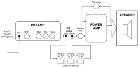
Guitarists now had TWO different points of the guitar amplifier to insert effects. Wah-wahs and gain boosts usually remained at the amp’s front INPUT. Reverbs, delays and tremolos usually went into the amp’s effects loop. This has been consistent through to today.
The method of placing external effects at 2 different points in the guitar amplifier’s circuitry is the Four-Cable Method (4CM). This is because it requires of least four-guitar cables to implement.
(Read more about 4CM here: https://www.rolandcorp.com.au/blog/gt-100-tip-four-cable-method )
Guitar players of the 1980’s now had high-gain amplifiers playable at any volume. The invention of the effects loop had solved the problem of how to make certain effects work with these new sounds. But what happened when players wanted to switch back to traditional CLEAN guitar tones again?
Multi-Channel Amps
For a guitar player in the early 1980’s to have access to both clean tones and heavily distorted tones at a gig, challenges were present. One option was to reset the whole amp in between songs. Another option was to use two amps – one for dirty, one for clean (such as the Roland JC-120).
Both were rather impractical solutions. Wouldn’t it be great if one amp could do it all?
Guitar amplifier designers realised that by using clever circuit design, they could build TWO preamp circuits into one guitar amplifier. These two preamp circuits could be individually preset – one for a clean tone and one for a distorted tone.
The power amp powered both preamp signals. By connecting a footswitch, the player could then select between these two individual channels.

The above diagram is typical of many modern amps that typically incorporate the aforementioned designs for maximum user flexibility.
The Roland Blues Cube series is a great example of a guitar amplifier that combines this modern flexibility, with the revered vintage tonality of amps from the 1950’s and 1960’s.
Other Common Amp Features/Terms
GAIN – As described above in the Preamp section, the gain control is essentially a simple volume control at the beginning of the preamp. In modern usage, the term GAIN refers to “distortion” because turning up the gain control in a master volume amp will cause the preamp to distort.
REVERB – An effect, found on-board many guitar amps, designed to replicate the echoic ambience of a large room. The Reverb circuit is located within the preamp and can be either digital or mechanical in nature.
TREMOLO – Another effect commonly found on vintage guitar amplifiers. Causes the volume of the amp to “throb” in and out in a regular fashion. Optical tremolo circuits are located within the preamp. “Bias” tremolo works by literally fading the operation of the power amp in and out.
BRIGHT SWITCH – A voicing switch that switches a capacitor in or out of circuit to enable brighter tones at lower volumes.
STANDBY SWITCH – Found only on tube amps relying on heater filaments to be hot in order to operate. The Standby Switch cuts the audio signal, while keeping the tube heaters active and ready for action. Not necessary on Solid-State designs.
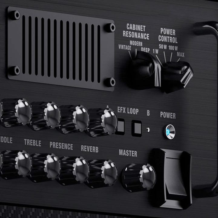
POWER CONTROL – Allows users to cut the available voltage to the power amp. This has the effect that the user can drive the amp hard for natural overdriven tones, at lower actual volumes.
BIAS – An internal control that enables a technician to fine tune the efficient operation of active devices within the amp. Not generally user adjustable.
RESONANCE – A tone control located within the negative feedback circuit. Works similarly to the PRESENCE control (see Negative Feedback chapter above) but on bass frequencies. Sometimes called DEPTH.
MIDI Control – Some amplifiers are able to use MIDI signals from other devices to control the amplifier’s functions, such as channel switching. Pioneered by Roland, MIDI (Musical Instrument Digital Interface) is a universal digital format. It allows any MIDI capable device, from any manufacturer to communicate with any other MIDI equipped device.
Contributed by Matt Walsham for the Roland Australia Blog
RELATED ARTICLES
Related Products